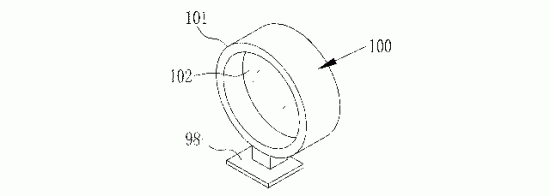
Nikon filed a patent (2012-257100) in Japan for a semi-transparent, see-through, rotating LCD screen. The idea behind this patent is to overlay the camera’s live view on a semi-transparent LCD display. This will allow a better tracking of fast moving objects and the photographer will be able to observe the entire scene beyond what is being shown in live view (similar to a rangefinder where you can see outside the frame lines). Nikon is basically trying to create a LCD screen version of the Fuji X100 hybrid viewfinder where optical and electronic display are combined into one. The patent includes several different solutions. Detailed description from the Japanese Patent Office (machine translated):
Detailed Description of the patent
The present invention relates to an electronic camera provided with a see-through display part.
Background of the Invention
In the electronic camera which adopts an electronic view finder (EVF), since the observation visual field in a finder is narrow, the object which is moving at high speed, for example is sometimes often missed out of a finder. There are also many electronic cameras which display a through image on the large-sized liquid crystal display section provided at the back face of the camera body, and perform flaming. However, since an observation visual field will become narrow further if zoom operation is carried out even if it carries out flaming, looking at the through image displayed on a large-sized back display, there is a possibility of missing an object from the screen of a back display. If it becomes such, it will become difficult to catch the object again in the view of a finder. So, a look is once removed to a photography person from a finder, and he takes the time and effort of checking the position of the object with the naked eye.
In the image displayed on EVF or a liquid crystal display section, after passing through digital conversion, an image processing, etc., in order to display on a display part, some gap (time lag) arises between a motion and screen display of a actual object. For this reason, when taking a picture of the object which runs by a sport etc., there is a possibility that it may delay for a while merely and may be reflected also with thinking that the shutter release was performed by the best timing.
In order to solve such a problem, the finder device of the video camera which applied the technology of the hologram to the sport finder is known (Patent document 1). This finder device carries out the superimposed display of the visual field image of the external world, and the taken image currently imaged with the image sensor by projecting a taken image on the screen which makes an object image transmit by a hologram.
In light of the above-mentioned circumstances, the present invention is inexpensive as a first purpose, and it is simple, and aims at providing the electronic camera provided with the see-through display part which an imaging range moreover tends to recognize visually, It is in providing the electronic camera devised so that consumption of a cell might be suppressed as much as possible as another purpose.
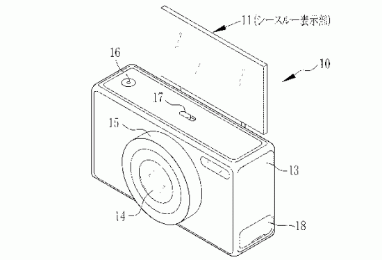
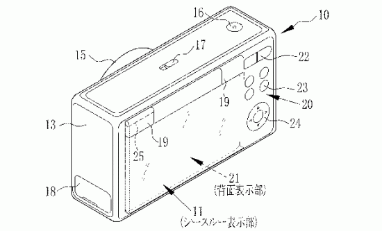
Drawing 1: It is the transverse-plane side perspective view showing the electronic camera of this embodiment, and the state where the see-through display part was rotated to the standing position is shown.
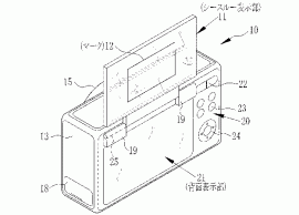
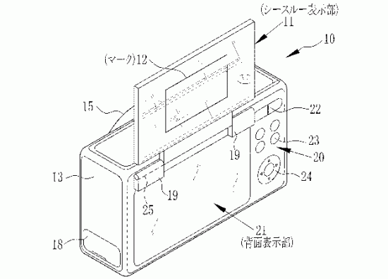
Drawing 2: It is a back side perspective view showing the electronic camera described by Fig.1, and the state where the see-through display part was rotated to the standing position is shown.
Drawing 3: It is a back side perspective view showing the electronic camera described by Fig.1, and the state where the see-through display part was rotated to the fall position is shown.
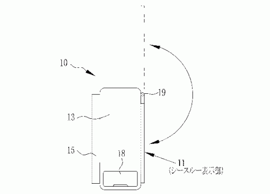
Drawing 4: It is a right side view showing the electronic camera described by Fig.1, and the state where the see-through display part was rotated to the fall position is shown.
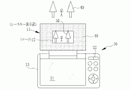
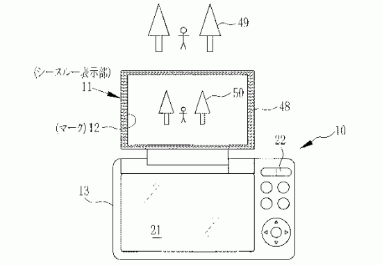
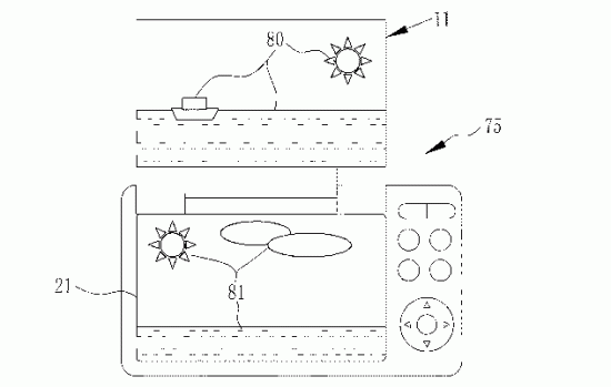
Drawing 7: It is an explanatory view showing the state where the mark which shows the imaging range at the time of a wide end was displayed on the see-through display part.
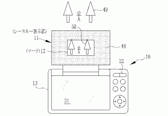
Drawing 8: It is an explanatory view showing the state where the mark which shows the imaging range at the time of a tele terminal was displayed on the see-through display part.
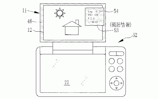
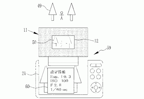
Drawing 9: It is an explanatory view showing the electronic camera of the embodiment which displayed film information on the see-through display part.
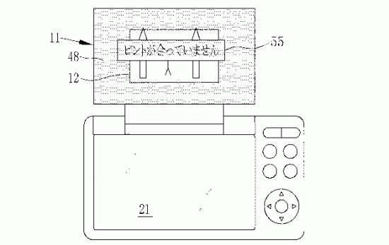
Drawing 11: It is an explanatory view showing the electronic camera of the embodiment which displayed error information on the see-through display part as film information.
Drawing 15: It is an explanatory view showing the state where the image in the mark displayed on a see-through display part was displayed on the back display, and the mark of the size at the time of a wide end is shown.
Drawing 16: It is an explanatory view showing the state where the image in the mark displayed on a see-through display part was displayed on the back display, and the mark of the size at the time of a tele terminal is shown.
Drawing 17: It is an explanatory view showing the electronic camera of the embodiment which displayed film information on the back display.
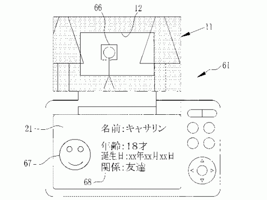
Drawing 20: It is an explanatory view showing the state where person information was displayed on the back display with the electronic camera described by Fig.18.
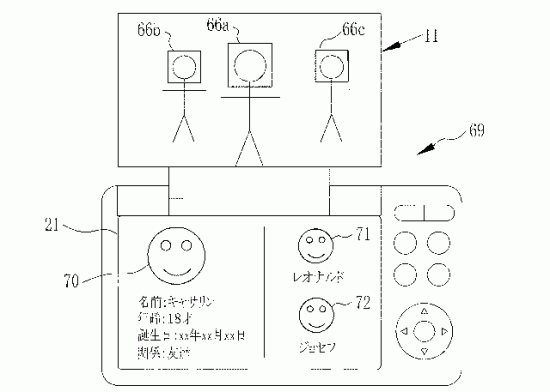
Drawing 21: It is an explanatory view showing the electronic camera of the embodiment in the case of displaying two or more person information on a back display.
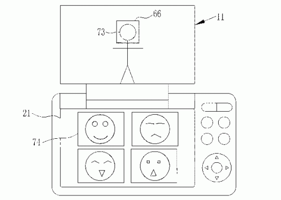
Drawing 22: It is an explanatory view showing the electronic camera of the embodiment in the case of displaying the image of the past similar to person information on a back display.
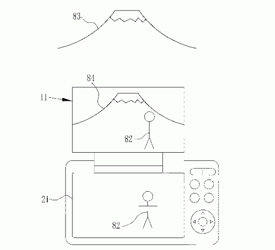
Drawing 25: It is an explanatory view showing the state where the image of the past similar to the image data incorporated from the image sensor was displayed on the back display.
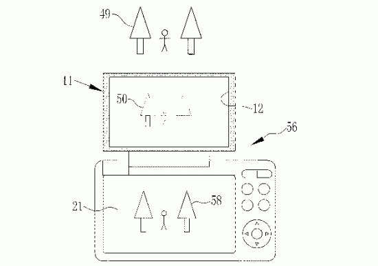
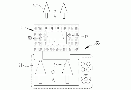
Drawing 26: It is an explanatory view showing the electronic camera of the embodiment which displayed the sample picture on the back display and the see-through display part.
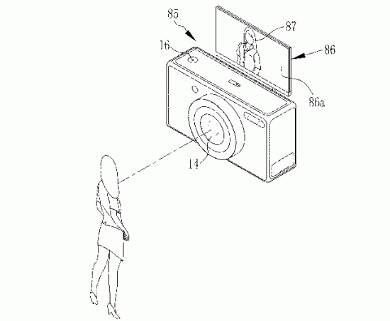
Drawing 28: It is a perspective view showing the electronic camera which chooses self-shot Mohd and displayed its face picture image on the front face of the see-through display part.
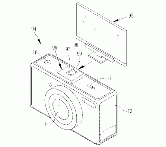
Drawing 31: A see-through display part is a perspective view showing the electronic camera attached enabling free attachment and detachment.
Drawing 32: It is a perspective view showing the telescopic see-through display part which can be detached and attached freely.
Via Egami
