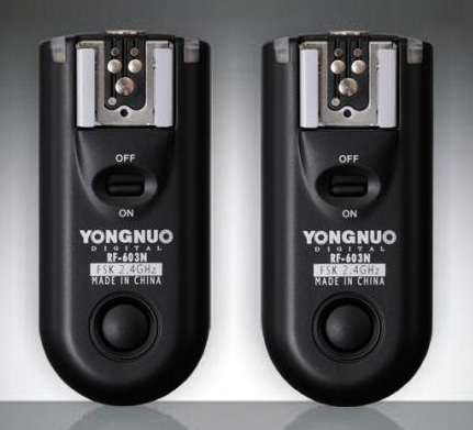
Next guest post by Otto Peter is on how to modify the Yongnuo RF603N wireless remote flash trigger (available on eBay) to fit non-Nikon flash trigger sources, like light meters, or any camera with a PC socket
The Yongnuo RF603N is a nice, cheap wireless remote flash trigger for Nikon cameras. It does well what it is designed for, but its flash capabilities can only be used when it sits in the hot shoe of a recent Nikon camera. I want to be able to trigger my flashes from a light meter, from my F2, or maybe even from my Linhof (which, admittedly, I have not taken out of its case for a decade).
Each Yongnuo unit consists of two components: a shutter remote and a flash remote. Each component can operate either as a receiver or as a transmitter. The shutter remote is a receiver by default, it turns into a transmitter when you press the button. The flash remote is a transmitter when it’s installed on a Nikon hot shoe (flash transmitter mode LED is on) and it’s a receiver when it’s not in a hot shoe. As a flash receiver, it outputs its trigger signal to its own hot shoe and to its PC terminal.
Obviously, what is needed is a way to switch the flash remote into transmitter mode without shoving it into a hot shoe. I said ‘switch’ because that’s how I implemented it – with a switch: I did not want the flash remote component to be permanently in transmitter mode. I wanted the flash remote in its original condition in one switch position and to make it act as a transmitter that can be triggered from the RF603N’s PC terminal in the other position. If you don’t care about that, you can leave out the switch – see below.
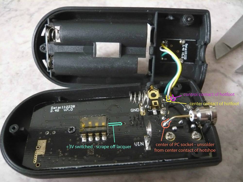
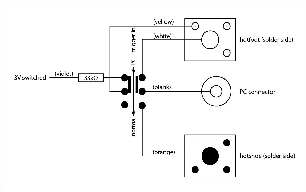
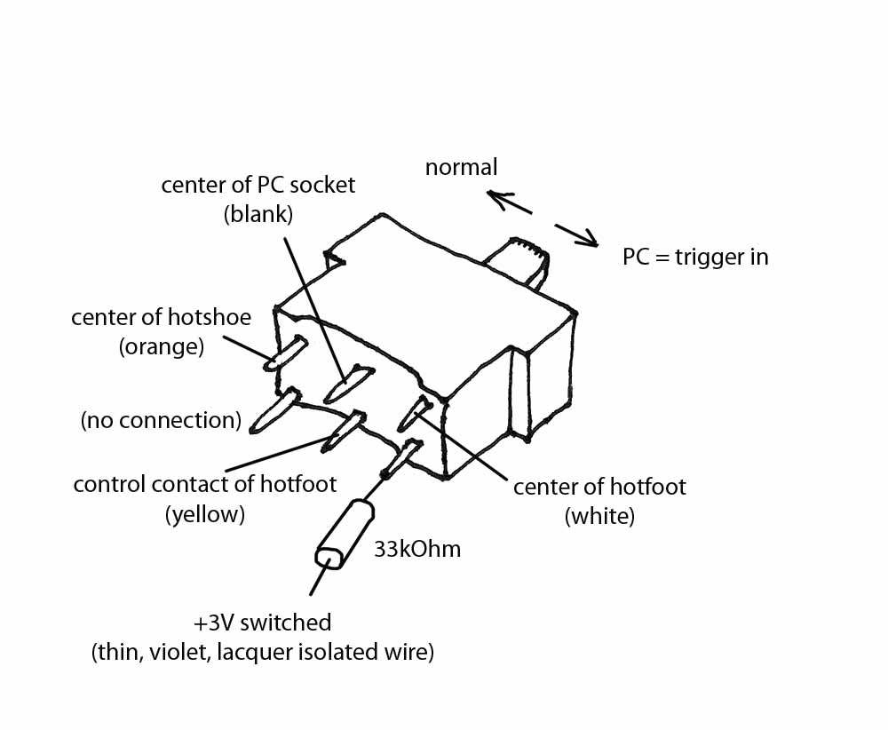
Opening the RF603N is easy – there are just three cross-head screws. Circuit board, hot shoe, power switch, button and PC terminal are in the upper shell, the connector that goes into the camera’s hot shoe is in the lower shell. The circuit board does not have to be removed, which simplifies matters, as the RF603N hot shoe and with it the upper shell is soldered directly to it. The bottom connector has three wires – ground (green), which is the hot shoe’s metal frame, flash trigger (white), which is the large center contact and a control line (yellow), which goes to the small contact towards the lens. This last wire carries some digital signal from the camera to the flash and is pulled to 5V at least part time. I tried to connect it to the plus pole of the battery through a resistor (few kOhms) and it worked: the flash transmitter indicator LED of the RF603N lit up and I could trigger a flash on another unit by shorting the center contact of the connector to the metal frame (or white to green). Almost there. Problem: If the resistor is just connected to the battery, it will draw power even if the RF603N is turned off. I needed to find the power supply after the on-off switch and I found it – a thin circuit board trace coming from the right hole where that switch sits on the other side of the board:
Now we are ready to step through the modifications:
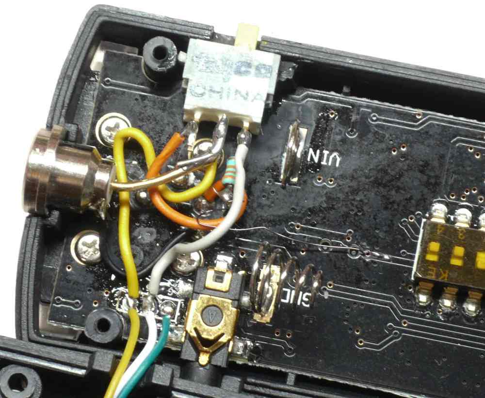
1 ‑ Find a suitable switch. Two poles and two positions are needed, and it has to be quite small. I used a Multicomp MC5SED1S105M2RES, available from Farnell for less than €3 in Europe (order number 2008805) and removed the metal clip and water proofing hood.
2 ‑ Cut and/or file a notch into the upper shell only (the one with the board in it). Don’t destroy the circuit board! I kept the piece I cut away and glued it in as lateral support for the switch.
3 ‑ Carefully chafe away few square millimeters of the lacquer covering the power supply trace on the circuit board. Don’t overdo it – it’s easy to remove the trace as well.
4 ‑ Unsolder the center contact of the PC terminal and solder it to one of the poles of the switch. This is a thick wire, stiff enough to keep the switch from being pushed into the case but a bit short, so I added a bit of extra wire to bridge a millimeter or two. Glue some small pieces of plastic to the shell to keep the switch from sliding sideways – I used liquid, solvent based plastic glue.
5 ‑ Connect a resistor (33kOhms or 47kOhms) between the switch and control contact of the hot foot. Connect all wires according to the circuit diagram and photographs. I suggest using a thin, lacquer isolated wire for the connection between switched power and switch as it’s more difficult to cleanly solder stranded wire to the thin trace on the board and the thin, supple wire does not rip off the trace too easily.
6 ‑ Close the case, see if it works.
I beg you not to over-estimate your abilities. It’s easy to ruin the circuit board by cutting into it, ripping off a trace, or peeling it off with too much heat for too long a time. I do not take responsibility if you turn your RF603N into electronic garbage. That said, here is what you have to do with a transmit-flash-only unit:
1 ‑ Carefully chafe away some square millimeters of the lacquer covering the power supply trace on the circuit board. Don’t overdo it – it is easy to remove the trace as well.
2 – Connect a resistor (33kOhms or 47kOhms) to the control contact of the hot foot. Use thin, lacquer isolated wire to connect it to the trace from step 1. I recommend not to solder the resistor directly to the trace as there is extreme danger of ripping off the trace.
3 – Unsolder the center contact of the PC terminal and connect it to the same board contact as the center contact of the hot foot (white wire) with a piece of wire. Be careful to prevent it from making contact with any other point on the board by putting a piece of electrical tape on the board.
4 ‑ Close the case, see if it works.
I have no idea about the Canon version of the RF603. It is likely that modifications are quite similar, but you’ll have to check for yourself.
Disclaimer: I do not take responsibility if you mess up – judge your abilities realistically. And while I usually know what I am doing in the realm of electronics, there is always a chance for error – you modify your RF603N completely at your own risk.
