Nikon’s curved image sensor patent (Google translation) will improve the sharpness in the corners of the image:
- Patent publication number 2010-109096
- Release date 2010/05/13
- Filing Date 2008/10/29
- Using a lens with field curvature aberration
- The image plane conversion element, sandwiched between the lens and image sensor
- Each pixel has a single optical transmission pipe
- Element corresponds to the surface curvature aberration
- As a countermeasure light falloff at edges, with a filter that only the central dimming
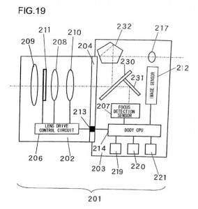
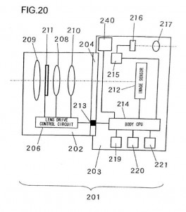
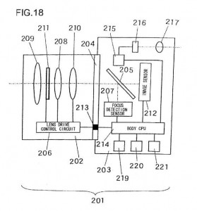
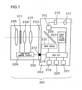
Nikon patent application 20100150539 is for a focus adjustment solution (see wikipedia’s explanation of the two different passive focus solutions: phase detection and contrast measurement). Different implementations are shown in this patent application: the first drawing is a camera with a half mirror, the second is mirrorless (EVIL) camera, the third implementations is without a prism (Pellix camera?) and in the last drawing the sensor is located under the mirror (instead of behind the mirror):
“Field of the invention: The present invention relates to a device that adjusts the focus of an imaging optical system, an imaging device equipped with the focus adjustment device and a focus adjustment method.
Description of the related art: There is a digital camera known in the related art (see Japanese Laid Open Patent Publication No. 2001-281530) that includes a focus detection sensor adopting a phase difference detection method and an image sensor. This digital camera first drives the imaging optical system to a point near the focus match position based upon the results of detection executed by the focus detection sensor, then detects the focus match position through a contrast detection method by using the output from the image sensor and executes fine adjustment to the focus match position. However, the contrast detection method and the phase difference detection method adopted in the camera in the related art described above are not perfectly compatible with each other since their focus detection principles are different and, for this reason, the correspondence of the focus detection results obtained through the two methods tends to be poor. For instance, there may be a photographic subject for which the focus can be detected successfully through the phase difference detection method but the focus detection cannot be executed successfully through the contrast detection method. In addition, while the focus may be detected with a high level of accuracy through the phase difference detection method for a given photographic subject, the accuracy of the focus detection for the same photographic subject executed through the contrast detection method may be poor. Under such circumstances, the imaging optical system may hunt for, and fail to reach the focus match point, the imaging optical system may be driven to an unexpected position or the imaging optical system may not move at all when the camera attempts to fine-adjust the position of the imaging optical system through the contrast detection method after driving the lens to a point near the focus match position through the phase difference detection method.”
The half mirror drawing is shown also in patent application US20100149361.
Patent Application 20100149649 is for a zoom eyepiece lens system.
Patent applications are not guarantee for upcoming products.

