Nikon’s patent 2012-189859 is exactly what designer Junho Yoon envisioned: a camera that you can throw up in the air in order to snap picture from above (see more camera design concepts here). The patent describes built-in velocity and acceleration sensors that can detect when to take pictures while in the air. In order to survive the fall, Nikon will make the camera “impact resistance” and will use a collapsible lens in order to protect the glass.
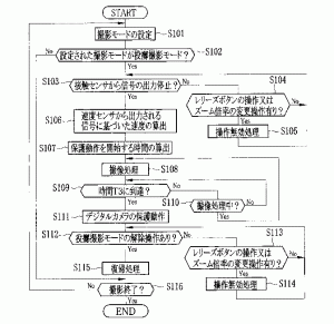
Some drawings and quotes taken directly from the Japanese patent application (machine translated):
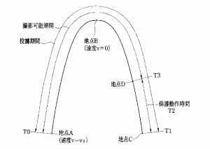
The above figure is showing the digital camera 10 when a user throws the digital camera 10 up, and change of the speed in a height direction in throw photographing mode. For example, if a user makes the point A the point which threw the digital camera 10 up, the speed v in the vertical direction of the digital camera 10 in this point A will serve as v0. Since gravity influences the digital camera 10 thrown as everyone knows, the speed v becomes small gradually and is eventually set to 0. When this speed v is set to 0, the digital camera 10 reaches the highest position (point B). Then, the digital camera 10 falls in response to the influence of gravitational acceleration (g), and the digital camera 10 is caught by the user at the point C.
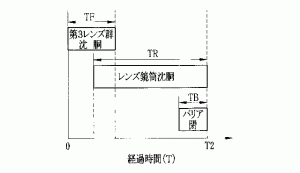
As shown in Fig.4, time [ to start the operation which makes the 3rd lens group 21c collapse ] TF will be dependent on the position of the 3rd lens group 21c, if speed of the 3rd lens group 21 at the time of collapsing is made into constant speed. The time TR to start the operation which makes the lens barrel 12 collapse will be dependent on the position of the position of the 1st tube 12a of the lens barrel 12, or the 2nd tube 12b or the 1st lens group 21a, and the 2nd lens group 21b, if the speed of the lens barrel 12 is set constant. It may start, in response to the fact that the operation which makes the 3rd lens group 21c collapse was completed, and the operation which makes this lens barrel 12 collapse may be started when the 3rd lens group 21c makes it collapse to a predetermined position. Since time [ to start the operation which closes the lens barrier 16 ] TB is constant, when the lens barrel 12 collapses to a position, it should just perform operation which closes the lens barrier 16. Thereby, the time T2 to start the protected operation of the digital camera 10 is computable.
Although the speed of the digital camera 10 when thrown is found in this embodiment from the signal outputted from a velocity sensor, it does not need to be limited to this and it is also possible to use an acceleration sensor instead of the velocity sensor 44. In this case, the speed calculation part 53 of CPU41 asks for a vertical acceleration component from the detecting signal outputted from an acceleration sensor, and computes the time quadrature of the vertical acceleration component in predetermined time as a speed of the digital camera 10 thrown. Thereby, even if it uses an acceleration sensor, the speed of a digital camera can be found like the case of a velocity sensor.
